
When using a 1/4 wavelength vertical antenna like the JPG-12, the radial system makes up the ground plane to produce the "mirror" other half of the antenna. Radial length and positioning can have a significant impact on the antenna's performance and behaviour. The coaxial feedline that connects the radio to the antenna carries the signal on its inner conductor, while the outer shielding is connected to the ground side of the antenna.
This means that a coaxial feedline directly connected to such an antenna will have its outer shielding layer act as a radial for the ground system.
The induced currents on the radials can have some significant effects on the radio and associated equipment, from making it RF-"hot" or energized, to causing equipment malfunction and even damage. It also means that reaching your hand towards the radio to change a setting will effectively alter one radial of the antenna, which can impact SWR and other things.
Some of these problems can be alleviated by introducing a common-mode choke at the antenna's feedpoint. Sometimes called a line isolator, a 1:1 balun, or a 1:1 un-un, a CMC uses induction to suppress common-mode current on the feedline's shielding, without disrupting the differential-mode current that carries the signal to the antenna.
Note: I don't fully understand how that works. Please consume grains of salt at this time.
Some common-mode current suppression can be achieved by using clamp-on ferrite beads. A current running through a ferrous loop will move some of its energy into the magnetic field. This can be adequate when the common-mode currents are small, but is likely to be inadequate in an antenna transmission scenario.
To produce significantly more suppression, we can coil the coaxial wiring into a spiral, producing an indictor. The effects can be amplified by coiling the coaxial around a magnetic permeable material like ferrite. Different ferrite mixes are more permeable at different frequencies; mix 31 and mix 43 are most common for HF frequency applications. You can use a calculator to get an idea of the materials involved.
I originally purchased an assembled CMC. The toroid turned out to be iron rather than ferrite, and the connectors were not assembled properly so it broke several times. The winding had 11 turns. Nevertheless, including it at the antenna's feedpoint had an immediately visible effect. With the antenna adjusted for minimum SWR on a particular frequency, without the CMC I could touch the shielding of the cable at the point that it plugged into the VNA and watch the Smith chart change significantly. With the CMC installed, touching the shielding had no visible effect at all. Before it broke, I connected it to the VNA to measure three important characteristics for a CMC: impedance match, insertion loss, and common-mode current suppression. An explanation of how to measure these can be found here and I describe my process below.
Each part of the transmission system, from the radio to the feedline to the properly tuned antenna, will have a characteristic impedance. In amateur radio, this is typically designed for 50 Ohms. We use RG58 for feedlines instead of RG59 because we want 50 Ohms impedance rather than 75 Ohms. Impedance mismatches resulted in high SWR values. Since the antenna and radio and feedline are designed for 50 Ohms, we want to ensure our CMC also has this characteristic impedance.
Measuring this with the VNA is straightforward. Calibrate the VNA for the frequency range of interest, say 5mhz-30mhz, using a 50 Ohm dummy load. Then insert the CMC between the VNA and the dummy load, and observe the Smith chart or SWR graph. Ideally it will be a perfect 1:1 impedance match across the entire frequency range. When I measured this one, it was about 1.02:1, close enough.
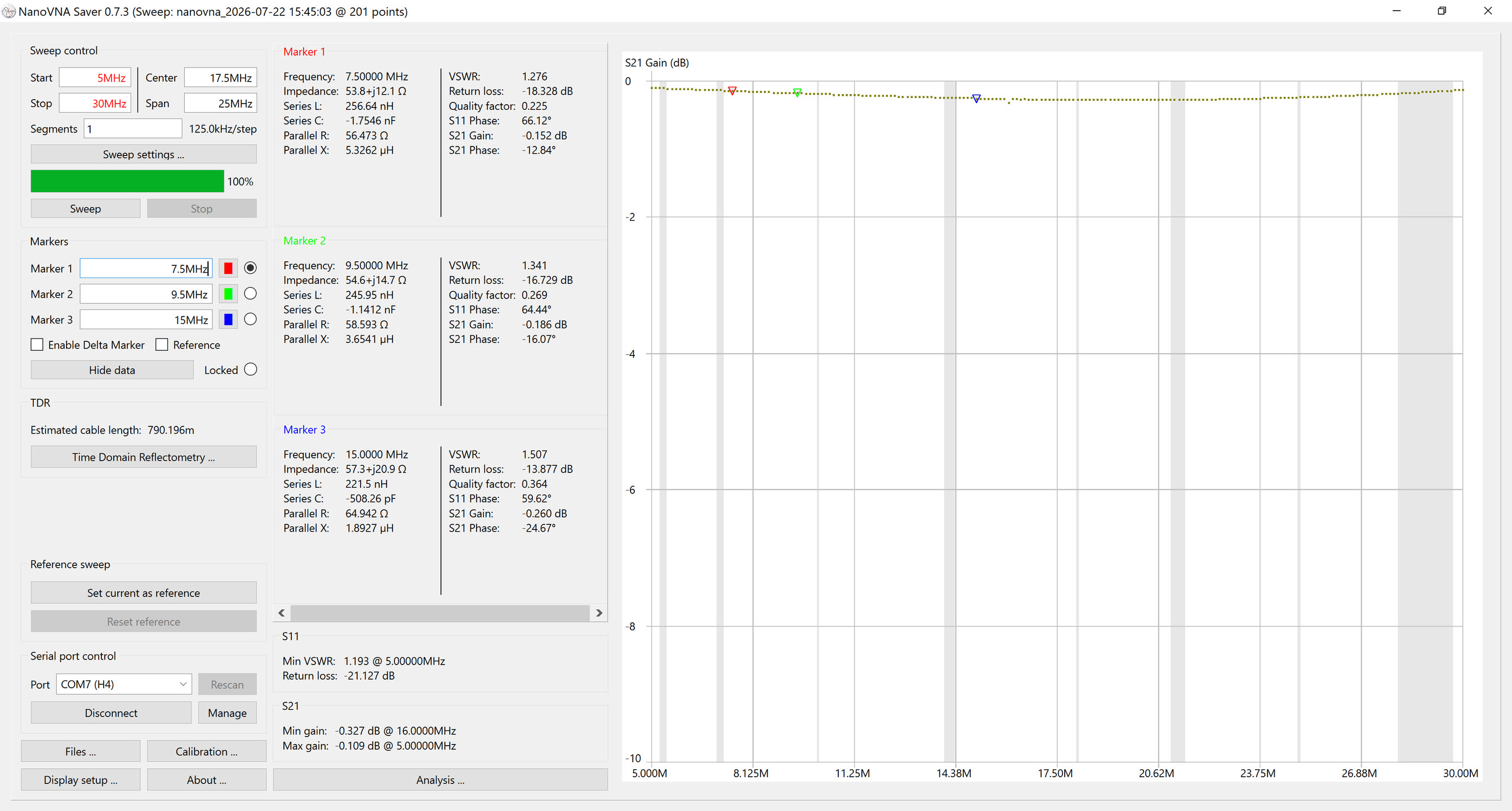
Next up is the insertion loss. Any time you put additional wire between the radio and the antenna, there is going to be some amount of resistive loss, and possibly some reactive loss. We want to minimize this loss, so that energy isn't spend warming up the CMC but rather goes into the air. To measure the insertion loss, we calibrate the VNA as above, including the extra steps of measuring isolation and thru. Then, connect the CMC from the S11 port to the S21 port, as if S11 were the radio and S21 were the antenna. The VNA graph for LogMag shows the gain (negative values mean loss) in dB caused by inserting the CMC. The theoretical ideal would be 0dB of loss. I remembered to get a screenshot of this, and you can see the insertion loss is between 0.1dB and 0.3dB, which again is close enough.
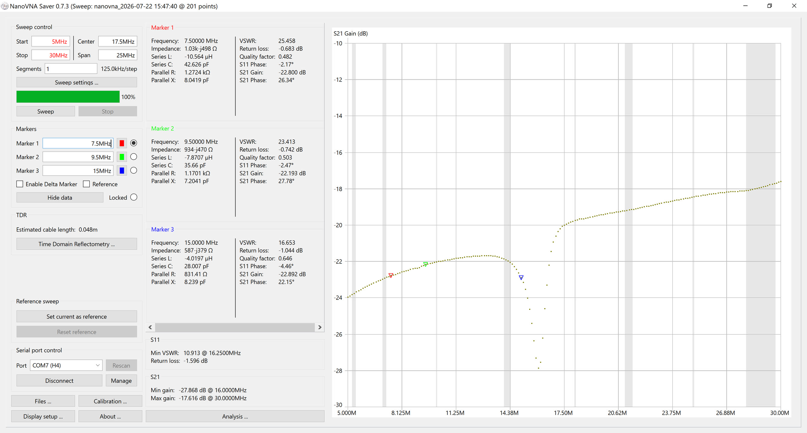
The two measurements so far have been checking to ensure that the CMC doesn't impact characteristics of the antenna system. But the goal of including the CMC is to have a significant impact on common-mode current. To measure this, we complete the calibration process as for insertion loss, but connect the centre conductors for S11 and S21 to the shielding layer on either end of the CMC. The outer conductors for S11 and S21 are connected together directly, bypassing the CMC. In the graph below, the suppression of the common-mode current varies by frequency. This is expected, since inductors naturally have different behaviours at different frequencies. The suppression ranged from -24dB at the low end of the frequency range to -17.6dB at the high end, about a 250-50x reduction in power. There's a resonance point around 16m. These numbers aren't great. I'd prefer to see at least 20dB suppression across the entire frequency range.
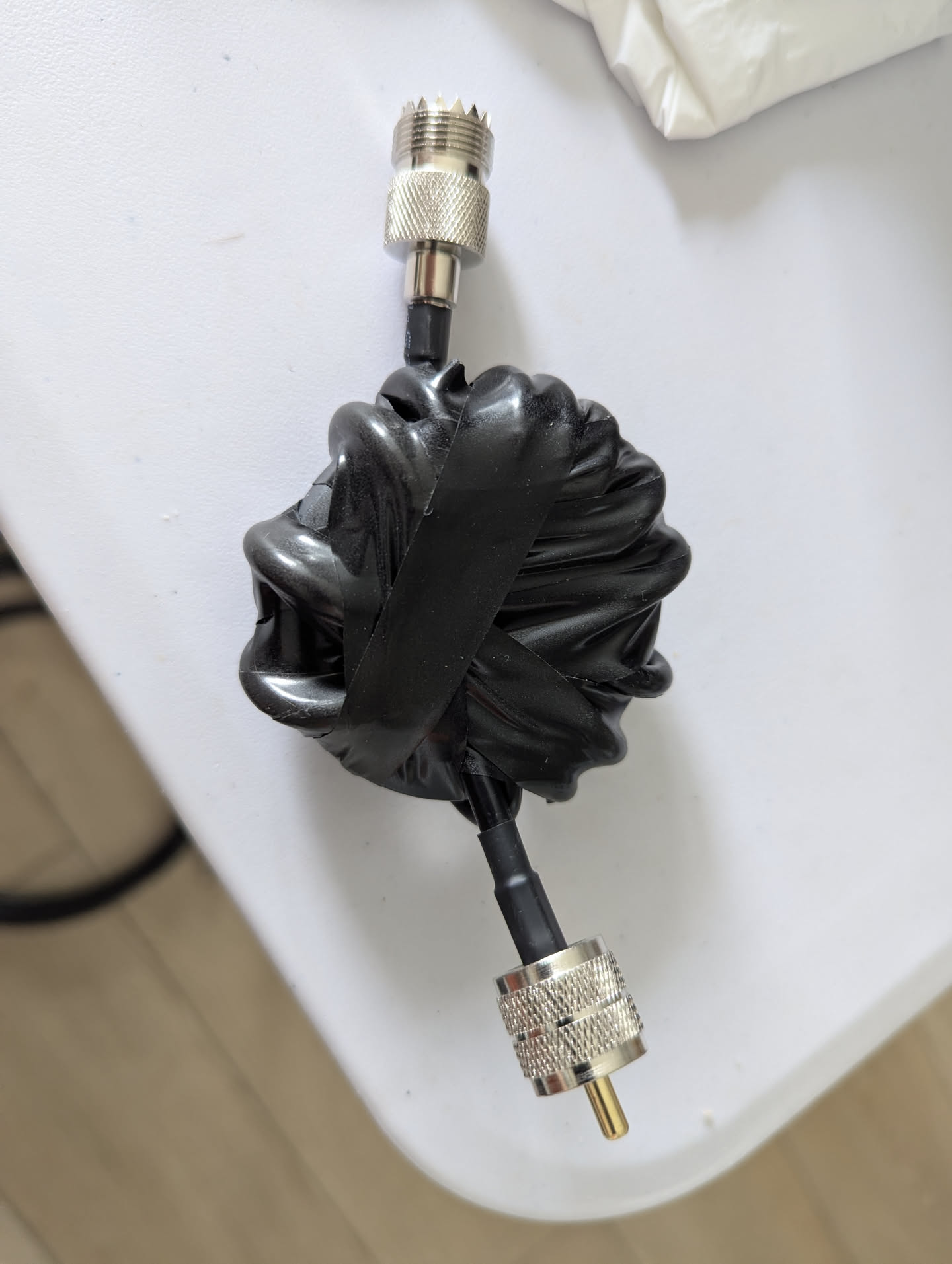
We can increase those numbers, and thus the positive impact of the CMC in our operating environment, in several ways. The two easiest are to use a better material than iron for the toroid, and to increase the number of windings. After this one broke a second time, I opted to assemble my own using a pre-made coaxial cable about 1m long and a mix 43 ferrite toroid. I had sufficient room to use 12 turns instead of 11.
Let's see the results:
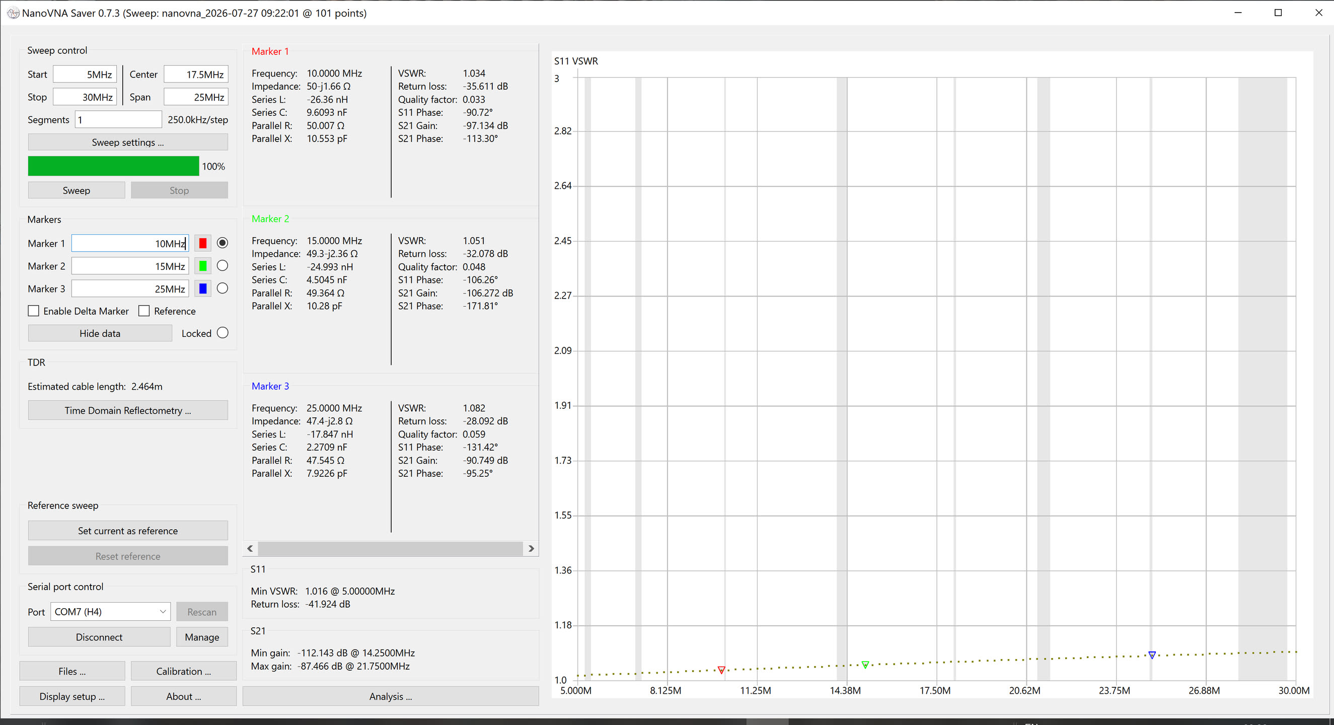
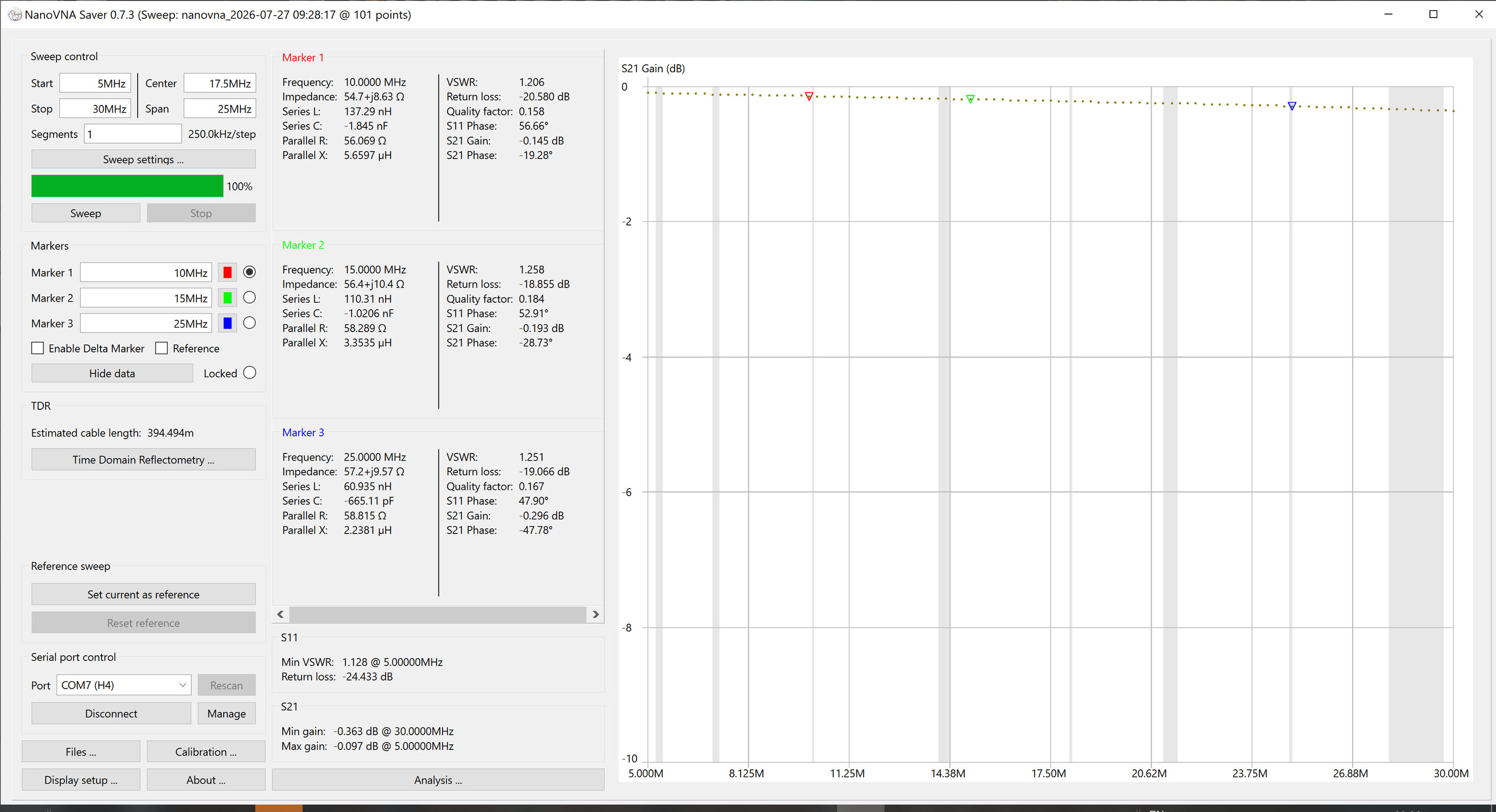
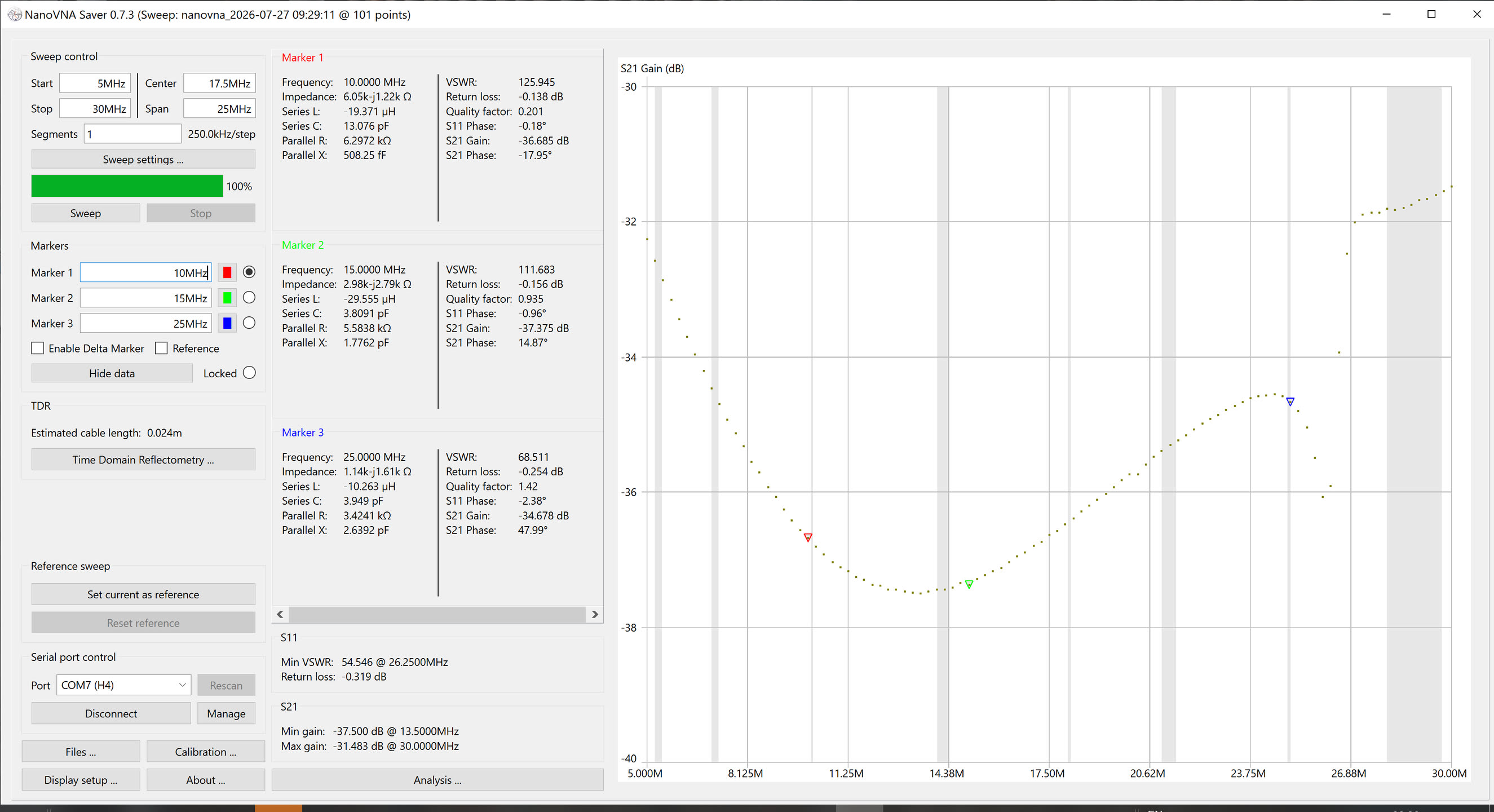
The impedance match goes from 1.016 to about 1.1, about the same. Insertion loss is between 0.1dB and 0.3dB, about the same. For suppression, we now have a resonance point around 26m, suppression across the range from -31.5dB to -37.5dB. This is a significant improvement over the previous model; remember that decibels are a logarithmic scale. This is a 1400-5600x reduction in common-mode wattage compared to 50-250x of the previous version.
Pages that link here: