
1/4 wavelength vertical antennas like the JPC-12 are quick to set up, easy to tune, omnidirectional, and have a pretty good takeoff angle. Their performance depends a lot on the effectiveness of the ground plane; minimizing ground loss is important for efficiency and good impedance matching. Carrying around a radiating mast that's 10m tall for working on 40m is cumbersome however, and lower bands even more so. To help alleviate this, one can trade some of the radiating element's efficiency for shorter length and more compact size. This is typically done with a loading coil.
Loading coils can be fixed or adjustable. My JPC-12 has an adjustable coil. Since the coil is pure inductance, no capacitance, it doesn't produce an RC circuit. Effectively, the coil electrically replaces some length of the radiating element, with higher inductance values representing more length. The more inductance you include in the radiating element, the shorter it will physically be at resonance. Thus the JPC-12 is capable of becoming resonant on 40m despite being about 4m long instead of 10m.
This is a trade-off. The part of the radiating element that's replaced by the coil does not radiate signal out into the air. The energy that would have gone into the air instead is loaded into the inductor's magnetic field. That means the more loading coil you include in your antenna, the less energy from your transmitter makes it into the atmosphere on its way to your communication partner. On QRP setups like the JPC-12 is designed for, that trade can be a costly one.
Current distribution along the radiating element is a good approximation of where the energy from the antenna is radiated into the air. A 1/2 wave dipole looks like half of a sine wave, with the maximum current at the centre and fading to none at the fixed endpoints. I like to say that it looks like a jump rope. For a 1/4 wave vertical, we cut that image in half and turn it 90 degrees. The other half is represented in the mirroring effect of the ground plane. So, if we set the vertical axis of a graph to be the height of the antenna above ground and the horizontal to be the amount of current present on that part of the antenna, our theoretical no-coil 1/4 vertical's current distribution would look something like this:
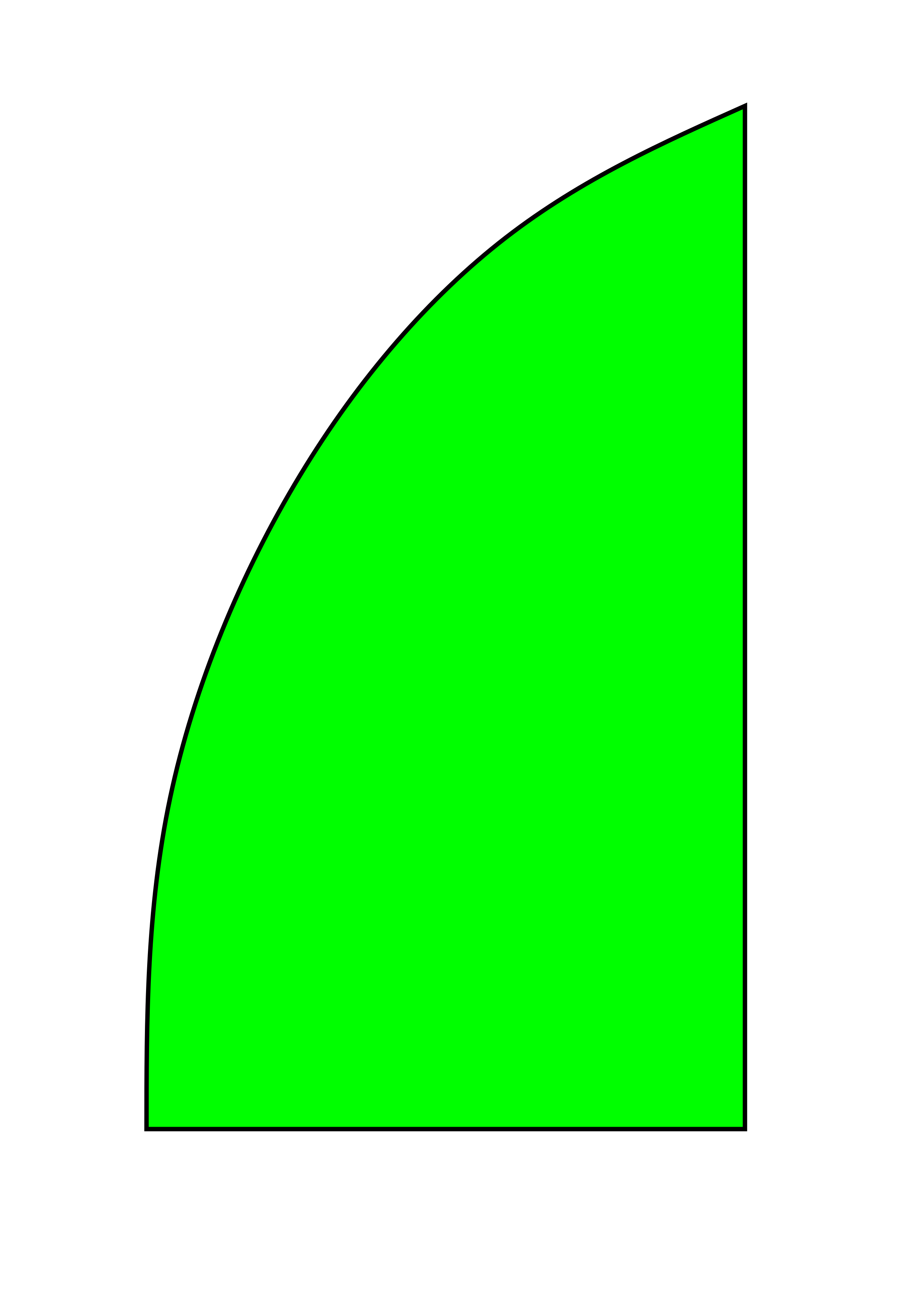
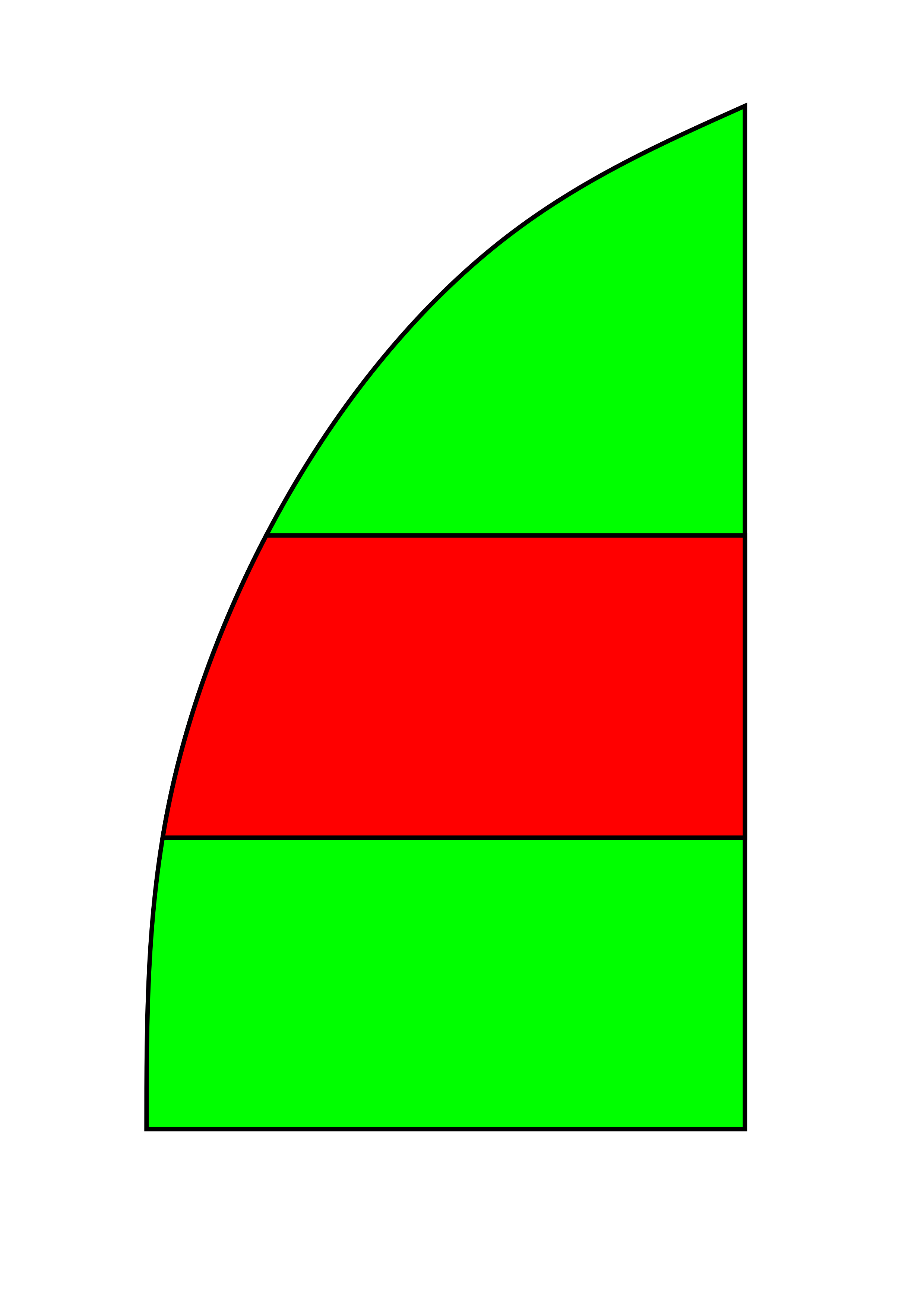
The JPC-12 includes its adjustable loading coil about 1.4m above the antenna's feed point at the ground. Above the coil is an adjustable telescoping section. When you insert a loading coil in the middle of the radiating element like the JPC-12 does, it replaces some of the radiating length, and its energy no longer makes it into the air. We can visualize that by marking that energy from the replaced radiating length in red to show it as lost:
There are other places one can insert the loading coil that have different characteristics. A common choice is the bottom of the radiating element near the ground. A "screwdriver" antenna is a common example of this. Placing the coil at the bottom of the antenna is mechanically convenient for the screwdriver's adjustment mechanism, but recall that the antenna's current distribution is highest near the feed point. Even with the same length of radiating element above the coil, the energy loss is significant:
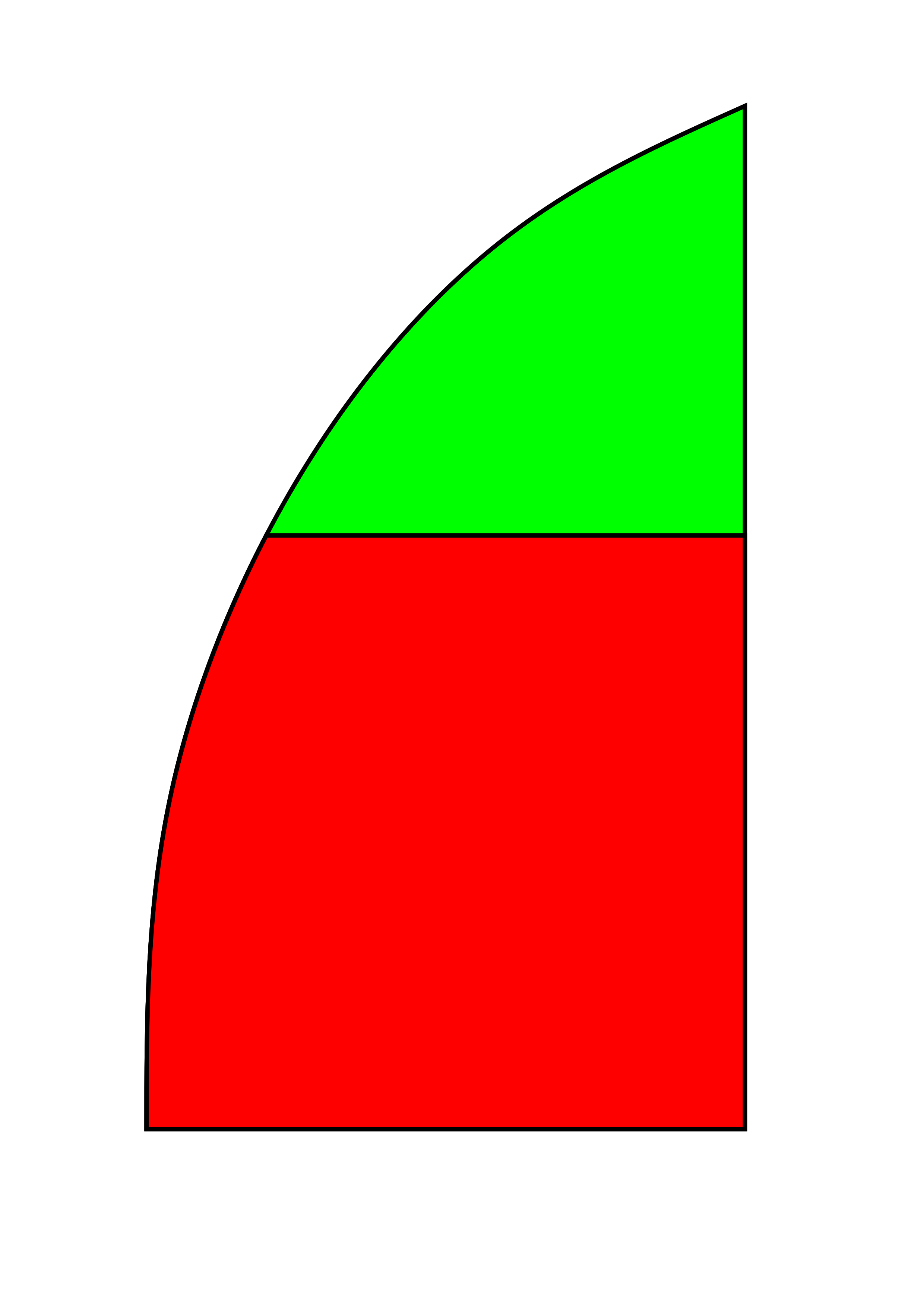
When replacing radiating length with a coil, it should be done as far from the feed point as is practical. The JPC-12 could be configured as a bottom-coil since the elements screw together. One could put the coil at the bottom, and put both the fixed and telescoping radiating elements above it. However, since the majority of the radiating current is at the bottom, that would be the worst place one could place the coil in terms of efficiency. The loss would be higher than when the coil is placed in the middle, even though the total physical length of radiating elements is the same.
Similarly, the coil in the JPC-12 could be adjusted to a higher inductance value, and the telescoping section above it could then be shortened to achieve resonance at the same frequency. This means that the coil is eating more of the transmitter's energy and less is making it into the air, so generally it is desirable to have the telescoping section extended as much as possible, but in cases of high winds or overhead obstruction it is an option.
Pages that link here: